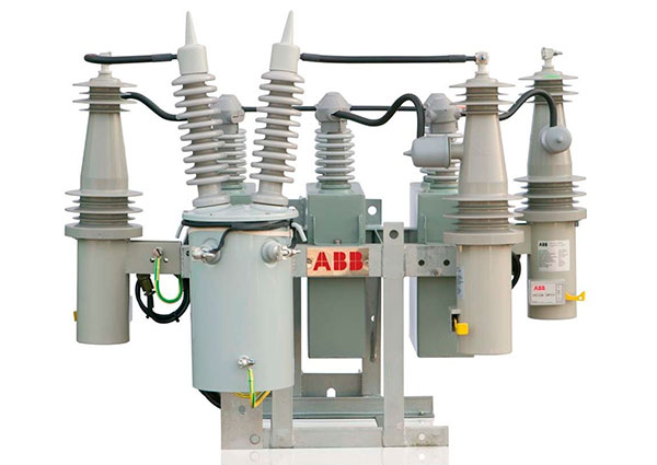
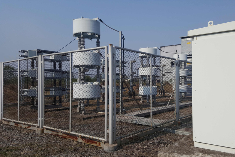
Medium Voltage (MV) capacitors are important devices in the systems of enterprises that use medium voltage power grids or have high power usage demands. What are the structure and working principle of MV capacitors, their uses, and notes for connection? All will be informed by Etinco in the following article.
What are Medium Voltage Capacitors?

Medium Voltage (MV) capacitors are types of power capacitors connected to a medium voltage electrical system, with the function of storing and releasing electrical energy in the circuit to stabilize the line voltage and compensate for reactive power. MV capacitors typically have voltage ratings from 3kV to 35kV and are categorized into 1-phase with two bushings or 3-phase with three bushings.
Structure and Specifications of Medium Voltage Capacitors
The MV capacitor has good insulation, consisting of two conductors which are two aluminum foil plates separated by an insulating paper layer, which are rolled up and placed in insulating oil inside a sealed aluminum alloy and polymer-coated shell. The terminals on the plates are brought out through insulating bushings to connect to the power source.
The MV capacitor has the following basic specifications:
- Fdm: Rated Frequency (Hz)
- Qdm: Rated Reactive Power (kVAr)
- Udm: Rated Voltage of the capacitor (kV)
- Cdm: Capacitance (μF)
Operating Principle of Medium Voltage Capacitors
Typically, the power transmitted from the source to the load consists of two types: active power and reactive power. Active power is the useful power for the equipment (with the unit W/kW). Reactive power is the useless power, with the unit VAr/ kVA. To reduce reactive power, the power factor cosφ must be compensated. The capacitor has the ability to compensate for reactive power, avoiding fines from the Electricity sector.

The operating principle of the MV capacitor is as follows: When the load is inductive, meaning the current is lagging the voltage, the MV capacitor is charged and produces a current that leads the voltage phase. The current from the capacitor balances the inductive load current to reduce reactive power and increase cosφ. The MV capacitor continuously charges and discharges to maintain a high cosφ threshold.
Applications of Medium Voltage Capacitors
MV capacitors offer the following benefits:
- Saving electricity bills: MV capacitors raise the power factor cosφ above the penalty threshold, ensuring the effective operation of the power grid, and simultaneously saving electricity costs.
- Reducing investment, maintenance, and upkeep costs for electrical equipment.
- Helping to minimize power losses and reduce voltage drop in the electrical network.
MV capacitors are often used in large-scale electrical systems such as factories, enterprises, etc. Additionally, this device is also used in wind power, solar power systems, and regional transmission grids to reduce transmission losses.
Some Compensation Methods on Medium Voltage Circuits
There are 3 common compensation methods used on medium voltage circuits:
- Fixed Compensation: Although the wiring diagram for this type of capacitor bank is simple and the investment cost is low, it is not compatible with the load profile. In case of a low-load period, it will produce reverse reactive power, causing additional power losses. Thus, fixed compensation is only suitable for base load compensation.
- Compensation based on cosφ Calculation: Precisely calculating the amount of cosφ needed for compensation to design the corresponding capacitor bank capacity placed at the substation. However, this form can cause a small amount of power loss on the low voltage grid. cosφ-based compensation is suitable for dedicated substations or those with a small radius of low voltage lines.
- Time-Based Compensation: Setting the compensation time and capacity according to the peak-time and off-peak time of the load, requiring the time settings to be compatible when the load fluctuates due to seasons, weather, or production characteristics.
Notes for Installation of Medium Voltage Capacitors
MV capacitors are usually in the form of 1-phase capacitors, with the rated voltage equal to the line-to-line voltage Ud. When connecting the capacitors to the MV grid, they should be connected in a delta configuration. With this configuration, the compensation capacity produced is more than 3 times greater than the star configuration, assuming the same capacitance C.

However, in some practical cases, the star configuration is still applied for MV capacitors, in which case the capacitor's withstand voltage must be √3 times less than when connected in delta. The withstand voltage of the capacitor is fixed. On average, increasing the withstand voltage by 10% will increase the capacitor's investment cost by about 20%, which is not optimal.
Example: To compensate 150kVAr for a 22kV grid, there are 2 ways:
- Method 1: Use 3 capacitors with a capacity of 50kVAr - 12.7kV connected in a star configuration. In this case, the voltage across the capacitor terminals is the phase voltage and equals 12.7kV - which is exactly the rated voltage of the capacitor unit. Each capacitor unit will deliver a power exactly equal to its rated power of 50kVAr, thus 3 capacitors deliver 150kVAr.
- Method 2: If connected in a delta configuration, 3 capacitors with a capacity of 50kVAr - 22kV must be selected. In this case, the voltage across the capacitor terminals will be equal to the rated voltage of the capacitor, and this equipment will deliver exactly the rated power, 3 units, each 50kVAr is 150kVAr.
Let's reverse the problem. If 3 capacitors of 50kVAr - 22kV are used and connected in a star configuration, the voltage across the capacitor terminals is only the phase voltage: 12,7kV = (1/√3)x22 (much lower than the rated voltage of the capacitor). Thus, the power delivered by the capacitor is only 1/3 of the rated power, meaning each capacitor only delivers 17.67kVAr, causing waste.
If 3 capacitors of 50kVAr - 12.7kV are used and connected in a delta configuration, the terminals of the capacitor are subjected to a voltage √3 times greater than the rated voltage of the capacitor, which can easily lead to a fire/explosion.
Accordingly, the capacitor units can only withstand the following overvoltages:
- 1.1 Un (rated voltage) for 12 hours each day
- 1.15 Un for 30 minutes each day
- 1.2 Un for 5 minutes
- 1.3 Un for 1 minute
Thus, before selecting and connecting capacitors, the most important factor is to calculate the appropriate capacitor compensation power for the rated voltage.
Above, Etinco has provided important information related to medium voltage capacitors, including: definition, structure, application, and method of selection, connection, and operation. To find out more information related to capacitors, you can visit: https://etinco.vn/tin-tuc/kien-thuc/.


